PdMA analysis: 6 fault zones in identifying the health of your engines
Electrical maintenance personnel have been limited for years to troubleshooting with no more than a multimeter and a megger. This, unfortunately, does not provide sufficient information to determine the type of fault occurring in a given electric motor.
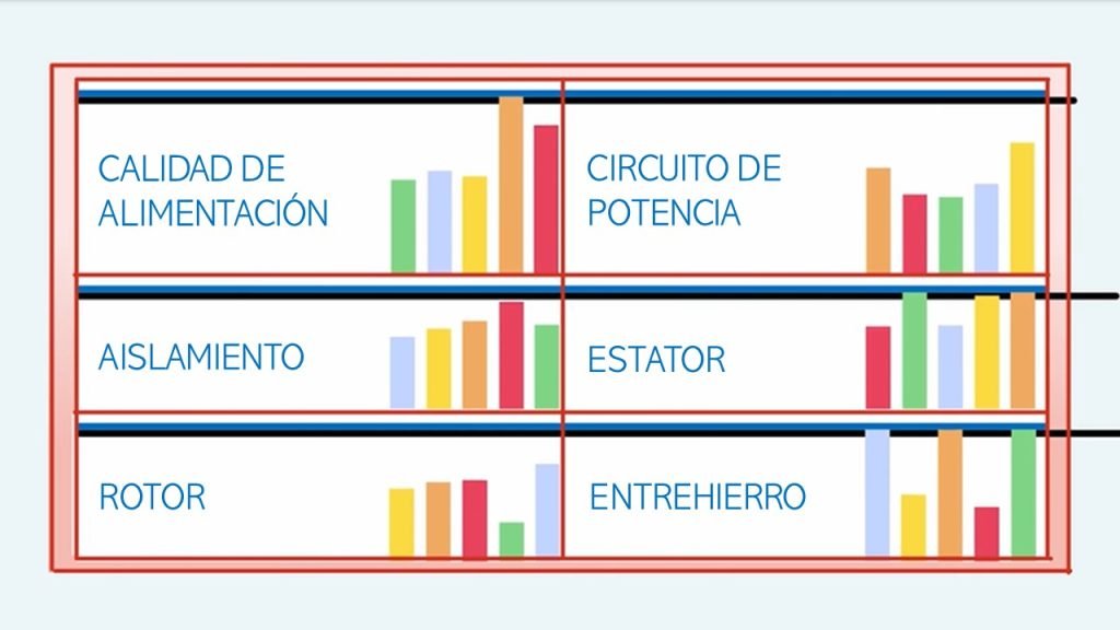
To safely report the electrical condition of a motor and ensure that the recommendation has been taken seriously, there are 6 areas of concern known as fault zones that should be checked during the search for a solution. Failure to account for all of these fault zones could result in omission of the problem and loss of credibility in the ability of the solution.
The 6 Electrical Fault Zones
- Power Quality.
- Power Circuit.
- Insulation.
- Stator.
- Rotor.
- Airgap.

Power Quality
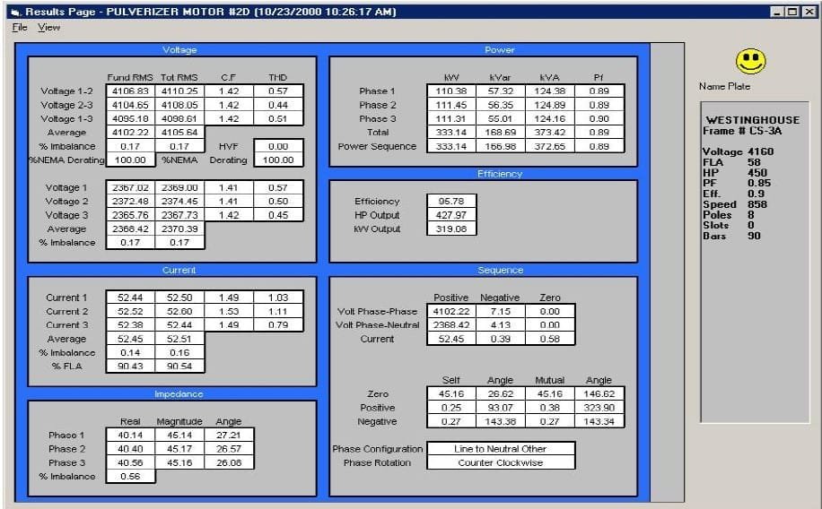
By developing a methodical step-by-step process, EMAX power analysis test results can quickly evaluate 3 of the 6 fault zones. Power quality refers to the condition of the signal voltage and current. Among the mechanisms that can impair power quality are non-linear single-phase and three-phase loads, variable frequency drives, starting and braking equipment, voltage spikes, among others. These can cause excessive harmonics on the distribution system which can result in overheating of the insulation system.
The MCEMAX power analysis test provides valuable detailed information to identify power quality in the distribution system. In addition, it also provides the data required for detailed evaluation of a system using variable frequency drives (phase-to-phase voltage, harmonic distortion, bus voltage, total harmonic distortion, vector diagram, voltage and current domains, etc.) and their effects on motor performance and condition. Testing with the MCEMAX gives you what you need to know what to do in terms of decisions that lead to a successful plan for maintaining optimum engine condition.
Power Circuit
A high resistance connection causes voltage and current imbalances, which significantly reduce the operating power. When a motor is fed with a faulty circuit, power unbalances such as negative sequence currents are generated.
As problems become more severe, power drops causing overheating of adjacent components, rotor damage, stator damage, seizure, decreased motor life, loss of efficiency, loss of motor or explosion. As long as the symptoms are rotor, stator, or insulation damage and the cause is in the power circuit, replacing the motor with a high resistance connection will only cause new failures in the new motor.

Insulation
Despite the recognized breakthroughs in the design of electrical equipment, the weak link in the chain is still the insulation system. Frequent failure of electrical equipment may be an indication of defective insulation.
Many external influences affect the life of electrical insulation systems. These influences include contamination of the insulation surface with chemicals in the environment that attack and destroy the molecular structure, physical damage due to improper handling or accidental shock, vibration and excessive heat due to proximity to the industrial process.
Voltage transients in the insulation conductors, as well as spikes caused by variable frequency drives, can lower the dielectric stress at the point of fault. Deterioration occurs in many forms and in many places at the same time. For example, chemical and/or heat changes in the molecular structure cause the insulating material to become conductive, allowing more current to be forced through it by the voltage, causing current leakage.
Stator
Stator analysis using EMAX technology is performed, evaluating the voltage and current phase relationships for each of the phases of an AC induction motor. These values are used to determine the impedance of each phase and display them as an impedance unbalance. The alarms show if the impedance unbalance exceeds the base or reference value.
Any change in the Real or Reactive component of a phase that is the duplicate of another phase will indicate a change that needs to be investigated. Another skill in acquiring data on current through the motor start cycle. Winding defects, such as open or shorted windings, will be identified as a change in the amplitude of the starting current.
Rotor
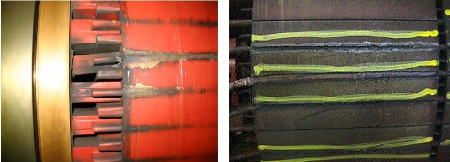
One method of assessing rotor health is the startup/startup test. The broken rotor bars create a high impedance in the rotor, resulting in a high impedance reflected in the stator, producing a drop in current and torque. Another method is the trend of the pole-passing amplitude in its sidebands. By increasing the PF, the amplitude of the sidebands is indicative of a modulating line current that is associated with rotor slip.
The third method for evaluating engine health with EMAX is high-frequency spectral analysis, sometimes referred to as the swirl effect. Broken or cracked bars create a phase shift in the air gap magnetic flux resulting in multiple FP sidebands below the fifth harmonic.
10% of motor failures are caused by rotor anomalies. This is equivalent in the number of engines in an average size of equal plants. Remember to always use the general spectrum of inspection methods listed above to confirm and extend the life of the engine, fixing the root cause of the problem and not the symptom.

Airgap
Eccentricity in the airgap will develop a magnetic flux imbalance between the stator and rotor during operation. This imbalance will lead to increased vibrations, mechanical wear and possibly friction between the rotor and stator.
Equipment that provides the information needed to make maintenance decisions about eccentricity severity is important. The MCEMAX provides easy evaluation during motor operation or de-energization. With the capability of RIC testing and frequency spectral analysis, the MCEMAX combines static and dynamic testing to provide a more comprehensive analysis of this fault zone, the airgap.
For more information, please contact our specialists.
Subscribe to our newsletter
Keep up to date with all the latest news on predictive maintenance and reliability!

